
Overview
Protecting Outdoor Solar-Equipment Support Structures
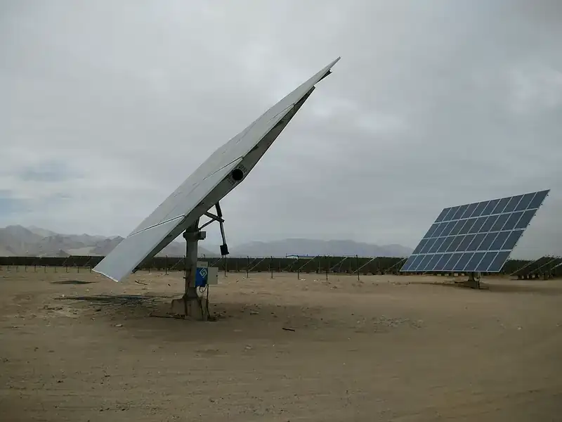
Outdoor supports combine ultraviolet exposure, rain, dust, fasteners, cut edges, dissimilar metals and difficult maintenance access.
Technical Articles
Outdoor supports combine ultraviolet exposure, rain, dust, fasteners, cut edges, dissimilar metals and difficult maintenance access.
Overview
Outdoor supports combine ultraviolet exposure, rain, dust, fasteners, cut edges, dissimilar metals and difficult maintenance access.
01
Outdoor supports combine ultraviolet exposure, rain, dust, fasteners, cut edges, dissimilar metals and difficult maintenance access. Inspection focuses on drainage, coating damage during assembly, crevices, electrical bonding points and ground-contact zones. Repair materials must remain compatible with the substrate and existing finish.
02
A solar-reflective surface reduces the fraction of incident solar energy absorbed by the roof or tank. Thermal emittance, colour stability, cleanliness, weathering, roof construction and the insulation below influence the complete building response.
03
Typical evidence includes deposits, local oxidation, thinning, hot spots, changes around welds or supports, cracking at transitions and damage concentrated in the gas path. A photograph records the condition but does not by itself prove temperature, composition or remaining life.
04
Continuous and peak temperature, cycling rate, shutdown cooling, gas composition, particle velocity, substrate thickness, geometry, access and required return-to-service time all influence the system decision.
05
Record the equipment zone, substrate, operating state and representative defects. Clean a small area where needed, distinguish deposits from substrate loss, confirm the condition of joints and supports, and agree a trial area before full work.
06
Possible measures include operating adjustment, removal of deposits, refractory or metal repair, improved sealing, insulation, heat recovery, erosion control and a compatible protective layer. A coating cannot replace a structural repair or an operating correction.
07
Select from verified service temperature, substrate, thermal cycling, gas or liquid medium, erosion, target function and the available curing window. Product data must be checked for the complete system rather than one headline property.
08
Accept the substrate before opening material. Remove oil, salts, dust, loose material and incompatible residues; create the specified cleanliness and profile; repair defects; and protect prepared surfaces from flash rust, condensation and recontamination.
09
Confirm material identity, batch, mixing, induction or thinning rules and usable time. Control air and substrate conditions, ventilation, wet or dry film build, stripe coats, overlaps, recoat windows and curing. Difficult geometry is coated from more than one direction. Inspection focuses on drainage, coating damage during assembly, crevices, electrical bonding points and ground-contact zones. Repair materials must remain compatible with the substrate and existing finish.
10
Use an inspection plan with hold points for preparation, environment, mixing, each layer, representative thickness, continuity and cure. Record nonconformities and corrections so the final dossier describes what was actually applied.
11
Frequent errors include coating contamination, trapping moisture, keeping an unsound old layer, applying one heavy pass, missing edges and backsides, exceeding the recoat window, confusing touch dry with full cure and returning equipment to service too early.
12
Create baseline photographs and identify high-risk details. Reinspect the same locations after operating cycles or scheduled shutdowns, clean surfaces before judging them and repair local damage while the surrounding system is still sound.
13
A reflective finish does not repair roof leaks, active corrosion or failed joints and is not the same as process-equipment insulation. Climate, roof use, existing insulation and winter conditions must be considered.
14
A reliable result comes from matching the real operating condition to a complete system, preparing the substrate consistently, controlling application and curing, and maintaining traceable records. Product selection is the consequence of that review, not the starting point.
Related technical content
Technical review
Project takeaway
Contact our technical team with the equipment, substrate, temperature and operating condition.