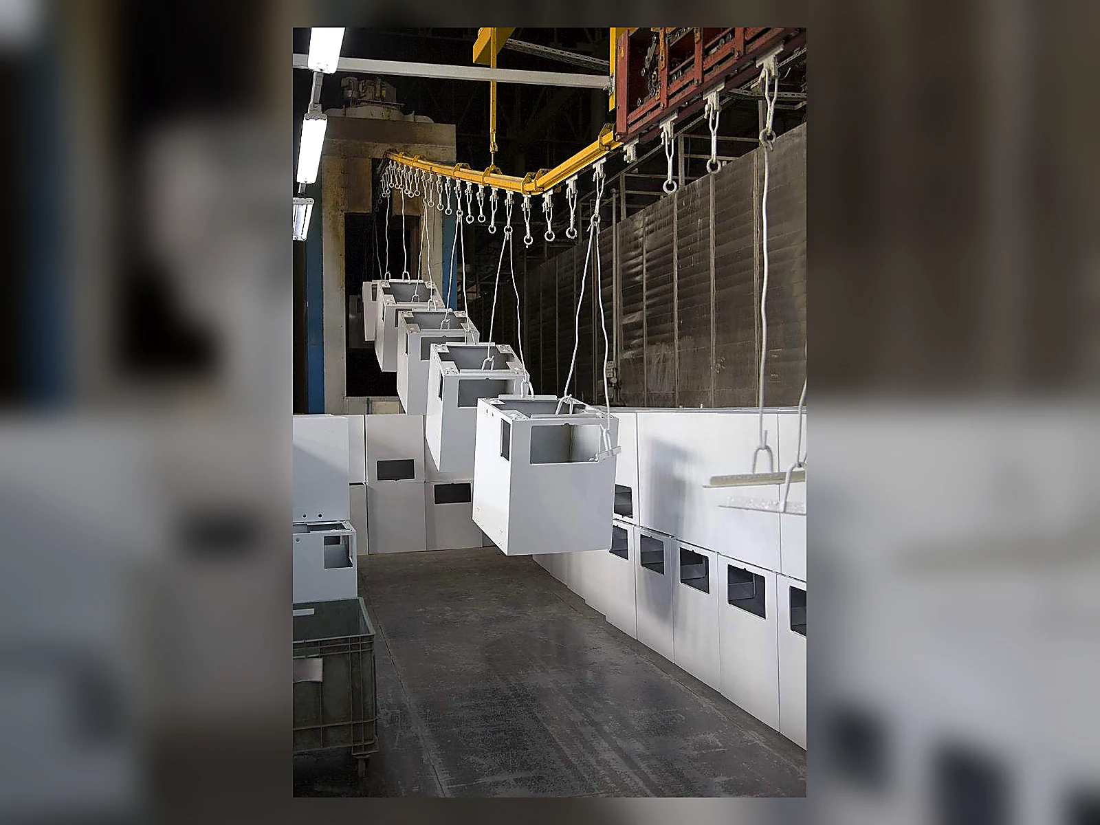
Thermal-Insulation Application on Complex Equipment

Application Guides

Thermal-Insulation Application on Complex Equipment

Irregular equipment cannot be treated as a straight pipe with more corners. Valves, flanges, housings, moving interfaces and removable sections require deliberate boundaries for masking, continuity, inspection and future access. This guide focuses on those application details rather than on generic thermal-insulation product selection.

Classify the equipment geometry and service interfaces

Create an equipment sketch that distinguishes fixed surfaces, moving parts, seals, bearing areas, fasteners, access covers, instruments and sections that must be removed during maintenance. Define the insulation boundary around function, not appearance.

Survey substrate condition, heat paths, and access

Record substrate type, existing layers, corrosion or contamination, local heat paths, supports and adjacent components. Mark areas that cannot be prepared, applied or inspected with the proposed access arrangement.

Separate bodies, bolted joints, stems, actuator interfaces and removable covers. Preserve access needed for operation, leak detection, fastening and future disassembly.

Identify clearances, vents, electrical parts, labels, sensors, lubrication points and other areas requiring masking or exclusion. Application must not obstruct movement, drainage, cooling or inspection.

Design masking and termination boundaries

Use traceable boundaries around excluded and removable components. Plan terminations so they can be inspected and repaired without creating hidden bridges, loose edges or material across a functional joint.

Build continuity across irregular details

Sequence accessible faces, recesses, brackets and transitions so difficult zones are not buried or shadowed. The selected product documents must control preparation, layer build and cure; this guide defines only the geometry-led execution logic.

  • Accept preparation before a recess becomes obscured.
  • Treat supports and penetrations as named inspection details.
  • Record unavoidable discontinuities and their technical disposition.
  • Keep service openings identifiable through every stage.

Preserve removable sections and maintenance access

Define how a removable cover or service zone will be opened, reinstated and inspected. Avoid a continuous finish that prevents required maintenance or makes later removal destructive to adjacent accepted work.

Inspect, document, and repair local details

Use the equipment sketch as the inspection record. Check terminations, interfaces, supports, masked boundaries, shadowed zones and local repairs, then link every exception to a disposition before the equipment is released.

Verification boundaries for complex equipment

Observable continuity and application quality do not establish heat-flow rate, energy savings or service life. Any thermal verification needs defined operating conditions and comparable measurement zones, while product suitability remains controlled by verified technical documents.

Related technical pathways

Project takeaway

Need technical documents or project guidance?

Send the operating condition and the document or application question you need reviewed.

Request technical support