
Corrosion Protection for Heat Exchangers and Finned Tubes

Technical Articles

Finned-Tube Heat Exchanger Corrosion and Coverage Review

Heat exchanger protection must account for exposure zones and the geometry between fins and tubes. Condensate, deposits, drainage paths and restricted access can produce different conditions across one unit and can also prevent cleaning, preparation and coating from reaching the intended surface.

Divide the exchanger into exposure and drainage zones

Map gas entry and exit, temperature transition areas, wash or moisture entry points, low points, drains, casing interfaces and bypass paths. Record which surfaces remain wet or collect deposits during normal operation and shutdown.

The finned bundle, tube-to-header area, casing and drainage details may require separate protection decisions even though they belong to one exchanger.

Identify the corrosion mechanism before selecting protection

Document the as-found condition before cleaning and compare it with operating and maintenance history. Look for patterns tied to gas direction, cold zones, deposits, drainage and areas that are difficult to wash or dry.

Identify where surface conditions can pass into a condensation regime during normal operation, low load or cooldown. If acidic condensation is suspected, the chemistry and operating boundary require separate investigation.

Deposits can alter gas flow, retain moisture and hide local corrosion. Record their distribution and remove representative areas using a method that does not destroy the evidence needed for diagnosis.

Evaluate fin spacing and hidden-surface access

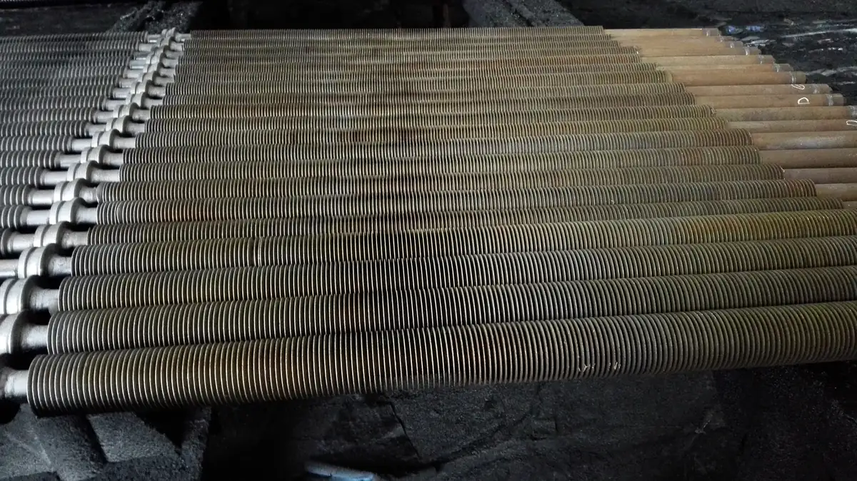
Confirm whether tools, cleaning media, inspection lighting and spray can reach between fins and around tube connections. Bent fins, tight spacing and bundle depth can create shadow zones that a front-face review will miss.

Test whether cleaning and preparation can reach the target surface

Select a representative area and demonstrate the full sequence from contamination removal to substrate acceptance. If the required surface condition cannot be achieved throughout the target geometry, revise the work boundary or access method before material is applied.

Plan coverage verification for fin backs and narrow gaps

Define inspection points at inlet and outlet zones, drainage areas, hidden surfaces and geometric transitions. Use the same location references for preparation records, application passes and final inspection so missed areas can be traced and repaired.

  • Inspect representative front and rear faces.
  • Check fin-to-tube and tube-to-header transitions.
  • Verify drain and low-point continuity.
  • Record areas that cannot be directly examined.

Define maintainable rather than theoretical protection

Protection should not block required drainage, inspection or future cleaning. Detail boundaries around removable panels, supports and access points so routine maintenance does not create uncontrolled breaks in the protective layer.

When dew-point investigation must be escalated

Escalate when damage concentrates at cold-end zones, appears after cooldown, aligns with persistent wet deposits or cannot be explained by external water entry alone. A dew-point investigation needs process and surface-condition evidence; appearance alone is insufficient.

Related technical pathways

Project takeaway

Need technical documents or project guidance?

Send the operating condition and the document or application question you need reviewed.

Request technical support